Blog
Surface Defects and their Control in Hot Dip Galvanized and Galvannealed Sheets
P. Saravanan, S Srikanth
R&D Centre for Iron and Steel,Steel Authority of India Limited, Ranchi-834 002 INDIA
Abstract: Inspite of significant advancements in continuous galvanizing technology and the resulting improvements in surface quality of hot dip galvanized and galvannealed coatings, producing entirely blemish- free coatings still poses a challenging task. Thus, surface defects are encountered intermittently in all continuous galvanizing and galvannealing lines. A thorough and in-depth understanding into the genesis and origin of these defects helps in identifying and employing prompt remedial countermeasures to alleviate their occurrences. The paper reviews the commonly confronted defects in continuously galvani zed and galvannealed sheet products along with their tell-tale characteristics as revealed by metallographic techniques and the means of eliminating them.
Although almost every tiny defect in a galvanized coating may look like a dross particle, dross entrapment actually accounts for only a small portion of the defects found in hot dip galvanized coatings. In fact, the average size of intermetallic particles suspended in a bath is normally less than 15 μm. Such small top-dross particles are often found buried in the coating underneath patches of oxide skin picked up mostly on the edges of the coated strip and are, as such, not visible and distinguishable. As a matter of fact, most defects occur because of a rough or mechanically damaged substrate surface, insufficient cleaning of the substrate, poor bath chemistry management and line equipment maintenance. Thus, galvanizers producing coated products must improve quality of the incoming steel strip, the line equipment, the in-line heat treatment regime and the coating bath in order to meet the stringent quality requirements for exposed automotive body panel applications. For lines producing both galvannealed as well as galvanized products, the additional challenges are to improve bath chemistry control in galvannealing campaigns to minimize bottom-dross formation and to develop a galvannealing to galvanizing transition procedure to either fully clear up or minimize the disturbance to the accumulated bottom dross.
1. INTRODUCTION
In integrated steel plants producing both hot and cold-rolled flat products, a significant proportion of cold-rolled sheet products are galvanized for use in construction and automotive sectors. Continuous hot dip galvanizing operation entails joining, cleaning, annealing and cooling of cold-rolled steel strip to 455-460 oC before hot dipping in molten zinc (Zn) bath at 455-460 oC followed by post-treatment processes involving air wiping, chromate passivation, temper-rolling and, finally, coiling. The quality requirements of galvanized sheet products encompass a prescribed uniform coating weight/ thickness, “spangle” size, lustre/ surface finish and formability along with adequate peel-off resistance and adherence of the coating with the steel substrate [1to 4]. Typically, hot dip galvanization baths make use of about 0.18-0.20% aluminium (Al), 0.10-0.20% lead (Pb) while restricting iron (Fe) to a level of 0.30-0.40% maximum for achieving high-quality coatings [1]. Al enhances the fluidity as well as the wettability of the zinc melt and also, aids in suppression of brittle Fe-Zn intermetallics at coating-steel interface by forming an “inhibition” or “barrier” layer of Fe2Al5 between the steel and the coating, thereby promoting the coating adhesion. Al is also known to improve the lustre and brightness of hot dip coatings and minimises the dross generation, to an extent, by forming an oxide (Al2O3) skin on the surface of molten zinc. Pb also lowers the surface tension and promotes the fluidity of molten zinc in much the same way as Al besides promoting the formation of “spangles” on the galvanized steel surface. Excess bath Fe, on the other hand, adversely affects the fluidity of molten Zn and leads to dull-appearing coatings with a poor peel-off resistance and adherence [1 and 2].
Although the surface quality of continuously hot-dip galvanized coatings has witnessed significant improvements in the recent years, it still remains a challenge to produce defect and blemish-free coatings for an exposed automotive body panel application. Continuous galvanizing of steel sheets basically involves chemical reactions between Fe, Zn and Al at temperatures above 450oC. As a consequence of bath-metal reactions, intermetallic particles constantly form in the bath, while Zn-Al oxide skin forms on the bath surface. Besides, the Fe-Zn intermetallics, which constitute the bottom dross, are in a continuous state of levitation due to the turbulence created by strip movement through the molten Zn bath. During continuous hot dip galvanizing, these intermetallic particles and surface skimmings can be easily dragged onto the coating. Intermetallic compounds can also grow on the surface of submerged hardware operating inside the bath. It is not uncommon for deteriorated surface quality of the submerged hardware to result in interior coating quality. Undesirable contaminants and pick-ups can be transferred from the hardware surfaces to the coatings [3].
The quality of the steel substrate can also strongly affect coating quality. Defects on the substrate surface, such as marks and indentations caused by mechanical damage, can be easily highlighted through the coating. Surface contaminants of the substrate, if not properly removed, can inevitably intervene with the coating process and result in bare spots. Most surface defects in galvanized steel sheets occur due to rough or mechanically damaged substrate surface, insufficient cleaning of the substrate or poor bath management and line equipment maintenance.
Surface defects can be large or small. But in order to be considered noticeable and rejectable, they must be large enough to be seen with the naked eye (The resolution limit of human eye is 0.1 mm). Consequently, an objectionable defect is larger than 100 μm. When viewed under an optical microscope at high magnifications, such a defect can extend to more than one view field.
Based on their origin, the surface defects encountered in galvanized and galvannealed sheet products can be broadly classified into six categories [5].
1. Defects originating from steel substrate
2. Defects associated with chemical cleaning
3. Defects originating from annealing furnace
4. Defects related to zinc bath
5. Defects originating from air jet wiping
6. Defects related to temper rolling
2. DEFECTS ORIGINATING FROM STEEL SUBSTRATE
Steel substrate defects, no matter how minute, do not get hidden by the zinc coating overlay in hot dip galvanized sheets. In fact, zinc magnifies those defects by reacting with the substrate, especially when the steel sheet is in full hard condition. Imperfections on the incoming steel sheet such as steel-making slivers, hot strip mill mechanical defects, scratches, surface damage during cold rolling, etc. cause Zn- Fe alloy outbursts at the steel-coating interface and/ or different dendritic zinc crystal orientation. Temper rolling makes these areas more prominent as a result of light reflectivity differences. Even tiny pimples in the substrate stand out and are mistakenly identified as dross. Some examples of commonly encountered defects relating to poor surface quality of steel sheet are discussed below [6 and 7].
2.1. Bare Spots, Exfoliation and Peel-Off of Galvanized Coatings
Bare spots are uncoated areas caused by incomplete wetting during dipping. Good wetting requires that all mill scale, rusts and oxides, oils and cleaning solutions be removed, exposing clean steel surface. Galvanizers commonly produce exposed-quality galvanized coatings in baths containing Al in excess of 0.2%. Coatings produced in such baths appear shinier and are preferred by users. However, at high levels of bath Al, the requirement of substrate surface cleanliness becomes much more critical for a good wetting. Frequently, tiny uncoated areas can be found in such coatings, as shown in Figs.1(a) and (b). Also, high-strength steels such as dual phase and TRIP steels contain alloying elements such as Si, Mn, Cr and Al, which can segregate to the steel surface and get converted to oxides during in-line heat treatment. As a result, wetting frequently becomes a problem. Exfoliation or peel-off refers to the delamination of galvanized coating under application of external stress, as in bending, and is usually the result of poor adhesion between the coating and the substrate. One of the main reasons for the occurrences of above surface defects in hot dip galvanized sheets is the poor surface cleanliness of the incoming cold rolled steel strip. Surface contaminants and cold rolling defects such as carry-over of cold rolling oil, emulsion, grease and oxidized rolling debris in the form of iron fines and particulates can leave residues on the strip inspite of in-line cleaning and annealing; leading to bare spots, on one hand, and poor adhesion at the coated areas on a galvanized steel sheet leading to coating exfoliation and peel-off, on the other hand.
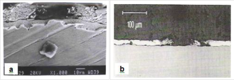
Fig1. Bare spots in hot dip galvanized coatings [a] SEM micrograph, [b] Optical micrograph
Figs.2(a), 2(b) and 2(c) depict the carry-over of cold rolling oil on a cold rolled strip sample and the typical appearance of bare spots encountered, as a consequence, in a hot dip galvanized steel sheet, manifesting as small and massive streaks respectively, with intermittently-dispersed thin zinc ribbons adhering to bare steel surface. Fig.2(d) shows a bare spot along with coating exfoliation and peel-off. Electron probe microanalysis (EPMA) in a through-thickness direction by back-scattered electron (BSE) imaging, X-ray elemental mapping and line profiling at the coated areas, as shown in Figs.3(a), (b) and (c), revealed delamination and presence of carbon at the steel-coating interface; indicative of carbonaceous residues resulting from burning of carry-over oil over the strip surface during annealing. Figs.4(a), (b) and (c) show a typical scanning electron micrograph taken along with energy-dispersive X-ray spectrometric (SEM-EDS) analyses of the surface features observed in a bare spot. The micrograph reveals random white patches on a dark-appearing uncoated and rough steel undersurface. Both dark and light areas reveal significant levels of carbon, suggestive of carbonaceous residues. The analysis confirms the white areas to be oxidized rolling debris consisting of iron fines from cold rolling. Figs.5(a), (b), (c), (d), (e) and (f) show SEM micrographs depicting both rolling debris at a bare spots as well as those entrapped at steel-coating interfaces, Zn-Fe intermetallic formation/ outbursts at coating-steel interface and the hemispherical appearance of the zinc ribbons on a bare spot with entrapped rolling debris and delamination between the steel and the coating.
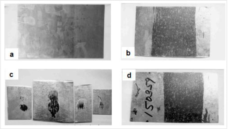
Fig2. Photographs depicting [a] carry-over of oil on cold rolled strip sample, [b] bare spots (massive streak), [c] bare spot (small streaks) and [d] bare spot with exfoliation/ peel-off of galvanized coating
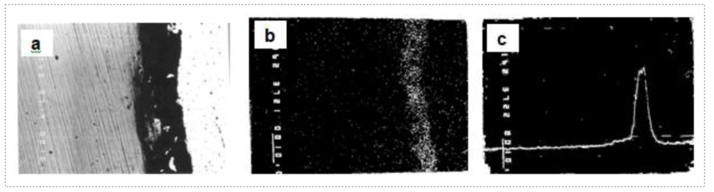
Fig3. EPMA of galvanized sheet specimen exhibiting massive bare spot depicting [a] BSE image of steel-coating interface with delamination, [b] X-ray mapping of carbon and [c] X-ray line profile of carbon
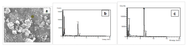
Fig4. SEM-EDS analysis of features in a bare spot [a] Micrograph revealing white features on a dark steel matrix, [b] EDS analysis from white feature showing Fe, O & C and [c] EDS analysis from dark areas revealing strong Fe peak & C
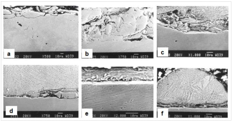
Fig5. SEM micrographs taken from a specimen with a bare spot showing [a]&[b] rolling debris at bare uncoated locations, [c]&[d] entrapped rolling debris at steel-coating interfaces, [e] Zn-Fe intermetallic outbursts at coating-steel interface and [f] hemispherical appearance of thin zinc ribbon adhering to bare steel, exhibiting delamination and entrapped rolling debris at coating-steel interface
2.2. Iron Fines in Coating
Frequently, the remnants of iron fines generated during cold rolling and subsequently carried-over on the strip surface get partly converted into intermetallic compounds and can be found in coatings. An example is shown in
Fig.6. Fe fines partly transformed into Fe-Zn intermetallic compounds in a Galvanized coating
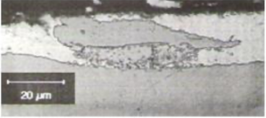
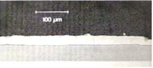
Fig7. Cross-sectional view through a shiny spot where the coating was thicker than surrounding coating and was flattened during temper-rolling
2.3. High Spots and Intermetallic Growth at Mechanically Damaged Substrate Surface
For a number of reasons, the reactivity of the substrate in molten galvanizing bath differs from one location to the other. Surface roughness and mechanical damage to the substrate during rolling processes, such as scratches, are the most common causes. Although galvanizing provides some levelling action to this unevenness on the substrate, surface roughness can still show through the coating, resulting in uneven coating thickness. In such cases, the resulting high spots associated with a thick coating are abraded in temper tolling. These areas are flatter than the surrounding coating and appear brighter. Fig.7 shows a cross-sectional view through a shiny spot. The coating was thicker than the surrounding coating and flattened by temper-rolling.
As is the case with iron fines, mechanical damage to the substrate can also induce Zn-Fe alloy growth (outbursts) in galvanizing. If the alloys grow through the coating thickness, gray or black spots will appear on the coating surface, as shown in Fig.8. High spots or bumps can also result from dross particle entrapment.
High Spots and Intermetallic Growth at Mechanically Damaged Substrate Surface
For a number of reasons, the reactivity of the substrate in molten galvanizing bath differs from one location to the other. Surface roughness and mechanical damage to the substrate during rolling processes, such as scratches, are the most common causes. Although galvanizing provides some levelling action to this unevenness on the substrate, surface roughness can still show through the coating, resulting in uneven coating thickness. In such cases, the resulting high spots associated with a thick coating are abraded in temper tolling. These areas are flatter than the surrounding coating and appear brighter. Fig.7 shows a cross-sectional view through a shiny spot. The coating was thicker than the surrounding coating and flattened by temper-rolling.
As is the case with iron fines, mechanical damage to the substrate can also induce Zn-Fe alloy growth (outbursts) in galvanizing. If the alloys grow through the coating thickness, gray or black spots will appear on the coating surface, as shown in Fig.8. High spots or bumps can also result from dross particle entrapment.
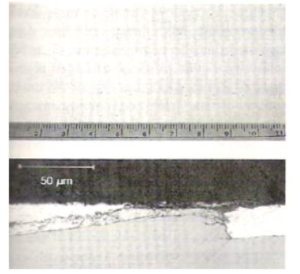
Fig8. Numerous black spots on a coating surface (top) caused by through-thickness growth of Zn-Fe intermetallics (bottom) induced by mechanical damage to the substrate
2.4. Substrate Scratches and Gouges
Fig.9(a) shows the visual appearance of tiny coated-over substrate scratches in a galvannealed coating, which were presumably caused by friction during in-line annealing of the strip. The defects manifested as tiny shiny spots on the non-prime side. However, the slightly-raised coating thickness at the defect locations caused print-through defects on the prime side after stamping [8]. Fig.9(b) shows the surface micrograph of the defect after coating removal, polishing and etching.
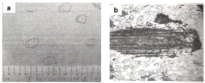
Fig9. Coated-over substrate scratch defect [a] Visual appearance and [b] Micrograph of the surface of the defect (140X)
2.5. Coating Defect Originating from Rolled-in Scale on Steel Substrate
Fig.10(a) shows the visual appearance of the coated-over defect in the form of a faint and short line in a galvannealed steel sheet. Figs.10(b), 10(c) and 10(d) show the surface micro-examination that revealed the presence of rolled-in scale particles, originating presumably from hot strip mill.
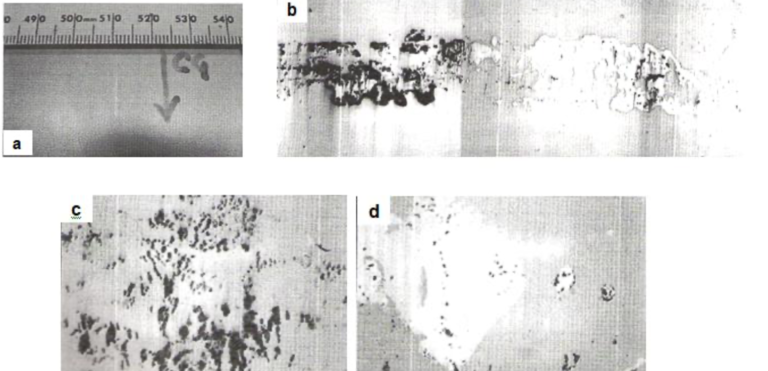
Fig10. Coating defect originating from rolled-in scale [a] Visual appearance of faint and short line defect, [b] Surface micrograph taken after polishing (35X), [c] Surface micrograph showing the embedded scale (350X) and [d] Micrograph showing entrapped scale in zinc pits (350X)
2.6. Tandem Rolled-in Scum in Galvannealed Coating
Figs.11(a) and 11(b) show the visual manifestation and cross-sectional microscopic view of coated- over rolled-in scum in a galvannealed coating, originating from a tandem cold rolling mill, respectively.
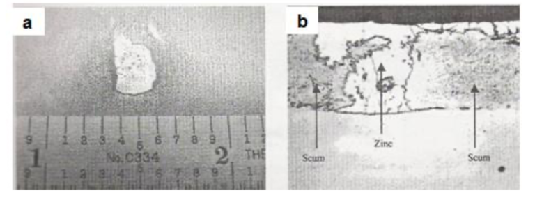
Fig11. Tandem rolled-in scum in a galvannealed coating [a] Coated-over scum and [b] Cross-sectional microscopic view of the defect (350X)
3. DEFECTS ASSOCIATED WITH CHEMICAL CLEANING
The surface contaminants on the incoming cold rolled strip consist of mainly iron fines, oil and dirt. Most hot dip coating lines producing exposed-quality galvanized sheet products for automotive applications have in-line chemical cleaning systems consisting variously of dunk, scrubber, electrolytic and water rinse tanks. Electrolytic cleaning, in particular, is not necessary, if the incoming strip is relatively clean with ~100 mg/m2 iron fines on its surface. Nevertheless, the objective of in- line cleaning section is to achieve ~20 mg/m2/side each of iron fines and oil on the strip surface. Otherwise, excessive carry-over of iron fines into the zinc bath causes undesirable dross formation and pickup and, sometimes, even bare spots on the strip due to inadequate zinc wettability. It is to be noted that grease spots, if present on strip surface, cannot be removed by alkaline cleaning; they convert to carbonaceous residues on the steel substrate surface during in-line annealing and cause poor wetting of molten zinc with steel and impair coating adhesion [9].
3.1. Grease on Galvanized Sheet
Figs.12(a) and 12(b) show the visual appearance and the cross-sectional microscopic view of the coated-over grease defect, respectively. Fig.12(c) shows the energy-dispersive X-ray spectrometric (EDS) analysis of the grease.
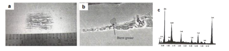
Fig12. Coated-over grease defect in galvanized sheet [a] Visual appearance of the defect, [b] Cross-sectional microscopic view (1000X) and [c] EDS analysis of coated-over grease
4. DEFECTS ORIGINATING FROM ANNEALING FURNACE
In continuous hot dip galvanizing operation, in-line strip annealing is performed not only to soften the cold rolled strip for achieving the desired mechanical properties, but also to clean the strip surface free from contaminants and oxides before immersing in the molten zinc bath. During the travel inside the furnace, the strip rides on several rolls and also undergoes various chemical reactions. In the direct- fired furnace (DFF), it is subjected to rapid heating in an atmosphere consisting of excess combustibles. Improper control of air/ fuel ratio in this furnace can cause undesirably high level of CO, which, in turn, could cause soot deposits on the strip. Such annealing-soot deposits are detrimental to coatability of the strip, manifesting in an ill-defined, interfacial alloy layer and bare spots in the zinc coating [10].
During the continuous line operation, strip oxidation in a properly maintained direct-fired furnace atmosphere is prevented. But in a discontinuous operational situation such as during an extended line stoppage, excessive strip oxidation may occur. In such a case, a portion of the resulting iron oxide is carried by the strip into the snout, thus contaminating the liquid zinc in the snout area. If this contaminated liquid zinc is not pumped out, bare spots can result in the coating.
In the radiant tube furnace (RTF), where the strip is subjected to indirect heating in a protective N2- H2 atmosphere, the overall strip cleanliness improves as long as the dew points and the oxygen are maintained at low levels. Otherwise, any furnace leaks or cracked radiant tubes can contaminate the furnace atmosphere and degrade the zinc coating adherence to the strip. Interestingly, grease leaks from the hearth roll bearings can even carburize the surface of ultra low carbon steels.
The new family of advanced high strength steels (AHSS), such as dual phase and transformation- induced plasticity (TRIP) steels with complex chemistries, undergo unique surface chemical changes during heat treating. Surface segregation and oxidation of alloying elements such as Si, Mn, Al, Cr, etc., not only significantly change the emmisivity, but also present coatability problems.
Another potential furnace-related quality problem is hearth-roll pickup, if the strip is allowed to ride on bare steel rolls. To prevent such pickup, the rolls are covered with cermet coatings or ceramic sleeves. Some examples of furnace-related coating defects are presented below.
4.1. Defects Due to Improper Furnace Atmosphere Control
Sometimes, during temporary loss of protective furnace atmosphere resulting in oxidizing conditions, a thin layer of iron oxide at the zinc-steel interface can occur which can become responsible for poor coating adherence. Such a defect might not be easily detectable during normal coating adherence testing but can be revealed only after forming, with scattered spots of poor adherence. Figs.13(a) and 13(b) show the visual appearance of a formed part with poor adherence and the cross-sectional microscopic view of the coating with the presence of the interfacial iron oxide layer, respectively.
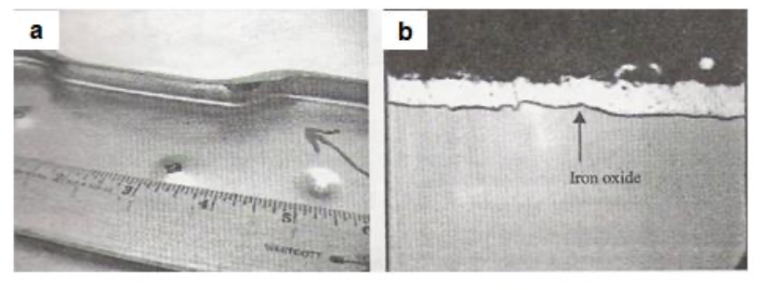
Fig13. Poor adherence due to interfacial iron oxide layer [a] Visual appearance of the formed part showing poor adherence and [b] Cross-sectional microscopic view of the specimen showing interfacial iron oxide
4.2. Grease Leak/ Carburization of Ultra Low Carbon Steel with a Galvannealed Coating
In one instance, excess application of grease to a hearth roll bearing caused the leakage of grease into the radiant tube furnace. The grease, consequently, underwent decomposition and formed carburizing furnace atmosphere, resulting in increased carbon and hence, yield point elongation in interstitial-free (IF) steel. As a result, closely spaced light coil breaks occurred as shown in Fig.14.
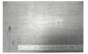
Fig14. Visual appearance of coil breaks in IF steel
4.3. Hearth-Roll Pickup in a Galvanized Sheet
Figs.15(a) and 15(b) show the visual appearance and the cross-sectional microscopic view of a coated-over hearth roll pickup defect, respectively. The coating-steel interface shows entrapped iron and iron oxide fragments.
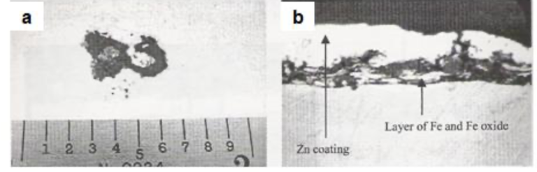
Fig15. Coated-over hearth-roll pickup scum defect [a] Visual appearance of the defect and [b] Cross-sectional microscopic view at the vicinity of the defect (700X)
4.4. Entrapped Argon Gas in a Galvannealed Coating
Fig.16(a) shows the visual appearance of a coating defect caused by entrapped gas from the galvannealing furnace atmosphere. Fig.16(b) shows the top view of a raised blister after removing the galvannealed coating and light surface polishing. After further polishing, several voids and a centreline crack were revealed [Fig.16(c)].
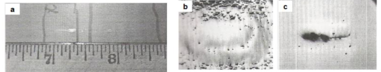
Fig16. Coating defect caused by entrapped gas from galvannealing furnace atmosphere [a] Visual appearance of the defect, [b] Micrograph of the surface after light polishing (35X) and [c] Same field after further polishing (140X)
5. DEFECTS RELATED TO GALVANIZING BATH
Poor zinc bath practices produce a wide variety of coating defects. Too high a strip immersion temperature in conjunction with low snout dew point can cause zinc vapourization at high line speeds. And when the aluminium-free zinc vapour condenses onto the strip before entering the zinc bath, Zn- Fe alloy outbursts occur which look like pimples or raised spots in the coating. Improper Al control (especially, during galvannealing to galvanizing transitions) combined with excessive bath temperature and iron fluctuation tend to create a drossy bath and cause dross pickup on pot rolls and entrapment of dross particles in the coating. Dross pickup on sinker roll tends to abrade the top side of the strip, causing streaky Zn-Fe alloy outbursts, especially on ultra low carbon steels. Heavy dross pickup on pot rolls can even produce dents in the strip. These problems can, however, be alleviated by employing proper zinc bath management. Some examples of the zinc bath related coating defects are discussed below [11].
5.1. Low Al Content Leading to Poor Adherence in Galvanized Sheet
After galvannealing to galvanizing transition, the effective Al content (%Total Al minus %Al consumed in formation of Fe2Al5 floating dross) in the zinc pot becomes relatively low (~0.11%). The low pot aluminium promotes the formation of the interfacial blocky zeta (ζ) phase particles. Figs.17(a) and 17(b) show interfacial blocky zeta phase particles that caused the poor coating adherence at two different magnifications, 2000X and 8000X, respectively.
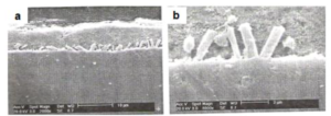
Fig17. Interfacial blocky zeta particles at the coating-steel interface in a sheet galvanized in low Al bath [a] Cross-sectional microscopic view at 2000X and [b] Same field at 8000X
5.2. Coated Surface Contamination/ Discolouration
Hot dip galvanized steel sheet samples exhibiting tiny surface blemishes that appeared as entrapped dross particles were examined under SEM in both secondary electron and back-scattered electron modes and were found to be either stains or small patches of oxide skin. Repeated examinations of the defect areas failed to reveal any dross particles. The stains and oxide film caused local discolouration of the coatings. A typical example of the defect is shown in Fig.18. The surface quality requirement of galvanized coatings for automotive applications is rather stringent. Therefore, handling of the coatings requires great care to prevent such stains and discolourations.
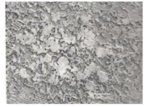
Fig18. Discolouration of galvanized sheet surface caused due to patches of oxide skin
5.3. Entrapped Dross Particles
Frequently, the edge of a coated strip contains dull patches on its surface. SEM-EDS analyses of one such galvanized sheet sample indicated that the defect areas were rich in oxygen. The dull patches were areas covered by oxide film, apparently picked up when the strip exited the bath. The oxide skins were broken up when the coating was air-wiped, resulting in shining veins within the dull patches. Cross-sectional examination using an optical microscope revealed numerous top-dross particles in the defect areas, as shown in Fig.19(a). Apparently, these dross particles were associated with the oxide film on the bath surface and dragged out together with the oxide skin. It appears that the bath surface was not skimmed sufficiently clean in the immediate vicinity of the exiting strip. Another such galvanized sheet specimen showing entrapped dross particles in the coating is shown in Fig.19(b). In one instance, a thicker gauge (~1.5 mm) hot dip galvanized sheet with non-spangled, dull and matte appearance of coating was found to exhibit entrapped particles of bottom dross, which were dispersed within the coating and conferred it with lacklustre appearance. The coated sample along with its SEM micrograph are depicted for illustration in Figs.20(a) and 20(b).
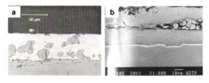
Fig19. Entrapped dross particles in galvanized coatings [a] Dross particles together with patch of oxide skin and [b] SEM view of the defect in another specimen
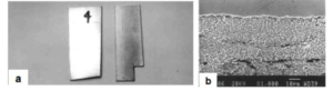
Fig20. Non-spangled, dull and matte coating appearance in hot dip galvanized sheet
[a] Photograph illustrating visual appearance and [b] SEM micrograph of the defect showing entrapped bottom dross particles in the coating
Large dross particles can also be entrapped in a coating individually. Such incidents occur mostly during galvannealing to galvanizing transition periods when the bath Al is quickly raised to a high level by adding brightener bars. A large number of top-dross particles are formed following the brightener addition. Bottom-dross particles accumulated in the galvannealing campaign will also be gradually converted to top dross according to the reaction:
2FeZn7 (Bottom dross) + 5Al = Fe2Al5Znx (Floating dross) + (14-x)Zn [1]
The partly-converted bottom-dross particles can remain suspended in the bath for a long time before they finally float to the bath surface. These particles are large because they have had a sufficient amount of time to grow while they settled on the bottom of the pot. Fig.21 shows a group of such dross particles, including a large one, generated during galvannealing to galvanizing bath-transition.
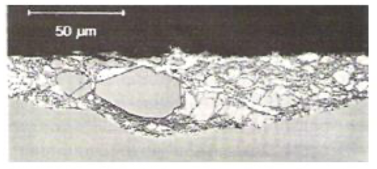
Fig21. Entrapped dross particles in a galvanized coating after galvannealing to galvanizing bath transition; these particles created print-through defects in the coating after temper-rolling
5.4. Dross in Galvannealed Coating
Excessive iron fines carry-over on the incoming strip surfaces could easily lead to the formation of dross particles inside the zinc bath. Fig.22(a) shows the visual appearance of the dross defect, which could be easily mistaken as a coated-over “scratch” defect. Fig.22(b) shows the SEM surface appearance of the dross pickup after polishing. The EDS analysis depicted in Fig.22(c) shows the typical chemistry of the dross particles.
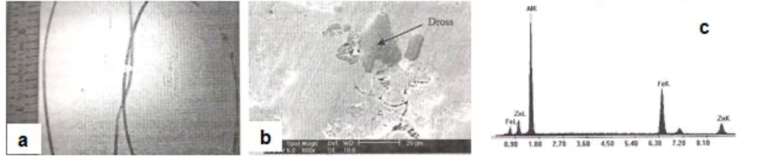
Fig22. Dross pickup defect in galvannealed coating [a] Visual appearance of the defect, [b] SEM view of the dross particles (800X) and [c] EDS analysis of the dross particles
5.5. Zinc Dust on Galvannealed Coating
In one instance, accumulated needle-shaped zinc dust particles from the touch rolls below the galvannealing furnace caused pickup on the strip. Fig.23(a) shows the visual appearance of the defect. Fig.23(b) shows the optical microscopic view of the zinc dust.
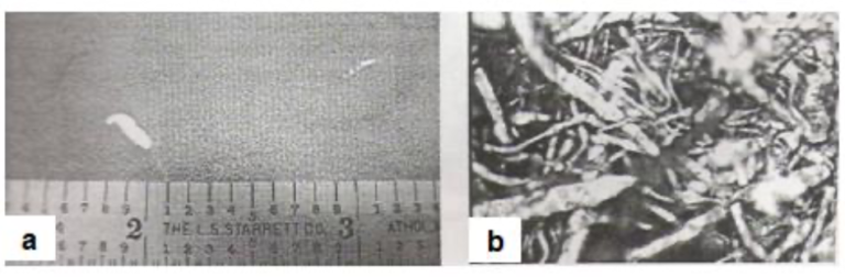
Fig23. Zinc dust pickup on galvannealed coating [a] Visual appearance of the defect and [b] Optical microscopic view of the zinc dust (700X)
5.6. Zinc Oxide in Snout
Excessive zinc vapourization can cause contamination of the liquid zinc in the snout with zinc oxide. This contaminated zinc coating on the strip can create a diffusion barrier at the coating-strip interface during galvannealing operation. Fig.24(a) shows the visual appearance of a dark line on galvannealed surface that was caused by zinc oxide pickup. Fig.24(b) shows the cross-sectional SEM view of the coating and the presence of the zinc oxide interlayer.
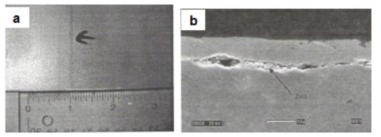
Fig.24 Zinc oxide pickup in snout as observed in a galvannealed coating {a] Visual appearance of the dark line defect and [b] Cross-sectional view under SEM revealing entrapped zinc oxide at the coating-steel interface
5.7. In-Situ Grown Zn-Fe Crystallites
Fig.25 shows Zn-Fe crystallites formed in-situ in a galvanized sheet during the hot dip coating process. The mechanism responsible for the formation of metastable Zn-Fe crystallites in coatings can be explained as follows. Thermodynamic calculations indicate that the transient Fe solubility at the coating-substrate interface is much higher than the equilibrium value maintained in the bulk of a bath. As a result, metastable Zn-Fe crystallites normally form in the coating at the moment when the strip contacts the molten galvanizing bath. With increasing dipping time, the dissolved Fe is partly used up by the formation of the “inhibition” layer and partly diffused into the main body of the bath. Consequently, the Fe solubility at the interface drops below the value necessary for maintaining the metastable equilibrium between the Zn-Fe metastable equilibrium between the Zn-Fe alloys and the surrounding liquid alloy, resulting in the dissolution of these crystallites. However, continuous galvanizing involves a rather short immersion time, typically less than five seconds which is sometimes too short for the metastable Zn-Fe crystallites to totally dissolve.
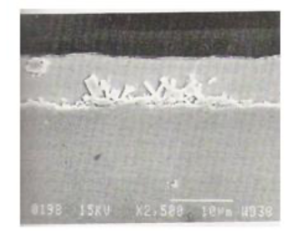
Fig25. Zn-Fe crystallites formed in a galvanized coating due to a relatively low bath effective Al level
The content of these Zn-Fe crystallites in a coating is a function of strip entry temperature, effective Al level in the bath, dipping time and substrate chemistry. For instance, when interstitial-free (IF) steel is galvanized under normal line operating conditions, metastable crystallites can be seen in the final coatings only when the effective Al level is below 0.15%. However, if the strip entry temperature is relatively high, or if the substrate chemistry is complex, metastable crystallites could form in a bath with an effective Al level as high as 0.18%. Normally, the adhesion of the coating is not adversely affected by the in-situ formed Zn-Fe intermetallic crystallites because they are mostly small zeta (; FeZn13) crystallites directly grown epitaxially from the substrate with no iron-rich Fe- Zn “gamma” (Г or Г’) phase forming between them. Nevertheless, the existence of these crystallites in the coating is a concern for some hot dip galvanizers [12].
6. DEFECTS ORIGINATING FROM AIR JET WIPING
During air jet wiping to control the coating thickness, header or jet lines can form. These are prominent longitudinal bands with very slightly thicker or thinner coating than the surrounding area, resulting from air jet disturbance either due to blockage of the knife slot with zinc dust, or deflection of the air jet due to zinc dust particles deposited on the knife lips.
Another prominent coating defect produced soon after wiping is coating sags or ripples. Sags tend to occur in heavy coatings on thick strip gauges or ripples in light coating on thin gauges, mainly in spangle-free coatings which do not solidify quickly in the upleg. Too smooth a strip surface, high strip and bath temperatures, excessive strip vibrations and fracturing of the oxide layer on the liquid zinc coating surface contribute to these defects.
Other undesirable defects associated with coating wiping are edge build-up resulting from saw tooth or damaged strip edges, improperly skimmed bath surface and improper coating wiping practice, and “caterpillar” defects. The “caterpillar” defects are caused mainly by non-uniform wetting of the strip surface with liquid zinc in conjunction with inclined flow lines from air jet wiping.
6.1. Caterpillar Defect in Galvanized Coating
Fig.26(a) shows the visual appearance of a caterpillar defect. Fig.26(b) shows the SEM close-up view of the flow lines associated with the defect.
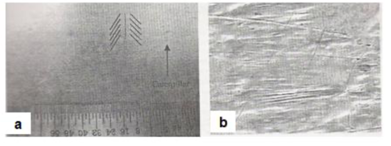
Fig26. Caterpillar coating defect originating from air wiping in a galvanized sheet [a] Visual appearance and [b] SEM view of the flow lines associated with the defect
6.2. Dents
In this group of defects, the coating is much thinner than the surrounding coating, but not completely missing. These thin spots or dents are caused by damage to the forming coating as it passes through the air-knives and the mini-spangle rig. Typical dent defects are shown in Figs.27(a) and 27(b). Judging by their morphology, the dents shown in Fig.27(a) were created by the impingement of droplets, originating most likely from the mini-spangle rig. The dent shown in Fig.27(b) is much less regular in shape. The flow lines, which were registered on the flanks of the dent, suggest that the wiping jet was disturbed locally by a solid particle entrapped at that location. A close examination of the cross-section of the relevant coating sample revealed numerous Fe fines in the coating. It is believed that, when the coating was passing through the air knives, a solid particle, presumably an Fe fine, was blown away from the coating by the air. Because the coating was already mushy and semi- solid, the dent failed to be levelled off by the surrounding coating.
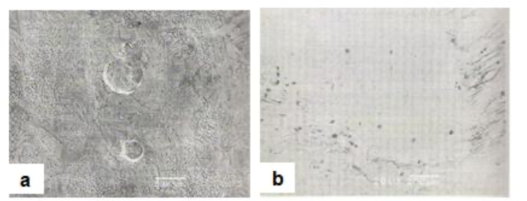
Fig27. Dent type defects in hot dip galvanized coatings [a] due to impingement of water droplets from mini- spangle rig and [b] due to temporary air wiping jet disturbance encountered as entrapped iron fines are blow away from the mushy, semi-solid coating
7. DEFECTS RELATED TO TEMPER-ROLLING
Due to the sliding friction between the hard work roll surface and soft zinc coating on the strip, zinc pickup on the work roll and consequent imprint on strip surface during rolling, especially on stand- alone temper mills even with wet rolling, is a frequent problem. Although work roll polishing and wet rolling solution practices have been developed to combat this problem, a practical solution to totally prevent pickup has yet to be developed.
8. CONCLUSIONS
It is technically difficult to produce entirely defect and blemish-free galvanized and galvannealed coatings for applications such as exposed automotive body panels. Coating defects are tiny, and instruments to identify their nature are not readily available to line operators. Consequently, most of the defects are believed to be dross pick-up. However, studies indicate that dross entrapment in coatings constitutes only a small portion of all the defects encountered in continuously galvanized sheets. Most defects are the result of poor substrate surface quality, insufficient strip surface cleaning, poor bath chemistry management and inadequate line equipment maintenance.
The entrapment of dross particles large enough to be spotted by unaided eyes may occur during galvannealing to galvanizing transitions when bottom-dross particles are floated up following a significant increase in the bath effective Al level. Such dross particles are accumulated at the bottom of a bath during the galvannealing campaign and grow to a large size (>100μm). If the line solely produces galvanized products and the bath surface is constantly skimmed, it is not likely that dross particle entrapment in coatings will occur frequently.
Studies have also shown that top-dross particles could be entrapped in coatings if bath surface oxide film is caught on the strip. Top-dross particles always segregate to the bath surface and co-exist with the oxide film. This finding points to the importance of maintaining a clean bath surface, free of oxide film.
Dross particles in coatings may also come from the following sources:
They grow in-situ at the coating-substrate interface because the effective Al level in the bath is relatively low and the strip entry temperature is relatively high. Under normal circumstances, the formation of discrete Zn-Fe crystallites in a coating is not detectable without sectioning the coating. Nor would they noticeably affect the adhesion and ductility of the coating.
If substrate surface is scratch & gouge-ridden, rough or mechanically damaged, the reactivity of the steel in galvanizing significantly increases. Zn-Fe crystallites can grow as outbursts in the coating, resulting in high spots with a thicker coating. These areas are noticeable after being abraded in skin passing because they reflect light differently.
On the other hand, if steel contains embedded Fe fines generated during cold rolling, these fines will partly convert into dross particles in galvanizing.
Production of defect-free exposed-quality galvanized coatings requires steels with high surface quality. These steels should be microscopically flat and smooth, free of mechanical damage. The cleaning section on a line must work effectively, otherwise wetting may become problematic in galvanizing. Galvanizers prefer to produce coatings in baths containing an Al level in excess of 0.2%. The requirement of substrate surface cleanliness is more critical for such baths.
Continuous hot dip galvanization of high-strength steels, such as dual-phase and TRIP steels, is under development for automotive applications. These steels normally contain a high level of alloying elements such as Si, Mn, Al and Cr. These elements are surface active and can be easily oxidized, even in an atmosphere which is reducing for Fe, when they segregate to the substrate surface during in-line heat treatment. It is envisaged that, when these newly-developed steels become the mainstream for the substrate, producing defect-free galvanized coatings will become even more challenging.
REFERENCES
- [1] Y-W. Kim, S-C. Kung, W.C. Sievert and R. Patil: “Surface Defects in Exposed Quality Hot-Dip Galvanized Steel”, 1989, ISIJ, 120-129.
- [2] N.-Y. Tang: “Thermodynamics and Kinetics of Alloy Formation in Galvanized Coatings”, Zinc-Based Steel Coating Systems: Production and Performance, TMS Conference, San Antonio, TX, USA, February 1998, TMS, PA, 3-12.
- [3] A. Komatsu, Y. Uchida, A. Andoh and K. Yamakawa: “Initial Stage of Reaction Between Sheet Steel and Molten Zn-0.2 mass% Al Alloy Bath”, GALVATECH’98, Chiba, Japan, September 20-23, 1998, ISIJ, 127-132.
- [4] J.S. Kim and J.-H Chung: “Galvannealing Behaviour of High Strength Galvanized Sheet Steels”, Galvanized Steel Sheet Forum- Automotive, London, UK, May 15-16, 2000, 103-108.
- [5] J. Mahieu, M. De Meyer and B.C. De Cooman: “Galvanizability of High Strength Steels for Automotive Application”, Galvanized Steel Sheet Forum- Automotive, London, UK, May 15-16, 2000, 185-196.
- [6] N.-Y. Tang and F.E. Goodwin: “A Study of Defects in Galvanized Coatings”, GALVATECH’01, Brussels, Belgium, June 26-28, 2001, CRM, 49-55.
- [7] F. Chen and R. Patil: “An in-depth analysis of various subtle coating defects of the 2000’s”, GALVATECH’04, 1055-1066.
- [8] A.Azimia, F.Ashrafizadeh, M.R.Toroghinejad, F.Shahriaric, “Metallurgical assessment of critical defects in continuous hot dip galvanized steel sheets”, Surface and Coatings Technology, Volume 206, Issue 21, 15 June 2012, Pages 4376-4383.
- [9] K. M. Moon et al., “Development of the Iron Elimination Technology of Acid Cleaning Solution of Hot Dip Galvanizing Process”, Advanced Materials Research, Vols. 472-475, pp. 367-370, 2012
- [10] A. RaviShankar, U. KamachiMudali, BaldevRaj, “Failure analysis of pin prick defects in galvannealed sheet – A case study”, Engineering Failure Analysis, Volume 16, Issue 7, October 2009, Pages 2485-2492.
- [11] Avik Mondal, Arup Kumar Halder, Soumilya Nayak, Amrendra Kumar, Anindita Chakraborty, Shweta Shukla, Sibasis Sahoo, Rajesh S.Pais, Monojit Dutta, “Root cause analysis of an uncommon surface defect on galvannealed steel sheet”, Engineering Failure Analysis, Volume 93, November 2018, pp.64-75.
- [12] Honglin Yang, Shengen Zhang, Jun Li, Xin Liu, Hua Wang, ”Effect of strip entry temperature on the formation of interfacial layer during hot-dip galvanizing of press-hardened steel” Surf.Coat. Techn., 240: 2013, pp. 269-274.
Citation: P. Saravanan & S Srikanth. “Surface Defects and their Control in Hot Dip Galvanized and Galvannealed Sheets” International Journal of Advanced Research in Chemical Science (IJARCS), vol. 5, no. 11, pp. 11-23, 2018. http://dx.doi.org/10.20431/ 2349-0403.0511002
Copyright: © 2018 Authors. This is an open-access article distributed under the terms of the Creative Commons Attribution License, which permits unrestricted use, distribution, and reproduction in any medium, provided the original author and source are credited.
